Sunday, 28 December 2014

Application of Auction Based Algorithm to Wireless Sensor Networks

Algorithm:

The algorithm initializes the price of each good to be unit, computes the worth of the initial endowment of each agent, and gives this money to each agent. All goods are initially fully unsold.
We will denote by p=(p1,p2,...,pn) the vector of prices of goods at any point in the algorithm. As p changes, the algorithm recomputes the value of each agent’s initial endowment and updates her money accordingly. Clearly, at the start of the algorithm, the total surplus (unspent) money of all agents is n.
At any point in the algorithm, a part of good j is sold at price pj and part of it is sold at (1+€)pj. The run of the algorithm is partitioned into iterations. Each iteration terminates when the price of some good is raised by a factor of (1+€). Each iteration is further partitioned into rounds. In a round, the algorithm considers agents one by one in some arbitrary but fixed order, say 1,2,...,m. If the agent being considered, i, has no surplus money, the algorithm moves to the next agent. Otherwise, it finds i’s optimal good, in terms of bang per buck, at current prices; say, it is good j. It then proceeds to execute the operation of outbid. This entails buying back good j from agents who have it at price pj and selling it to i at price pj(1+€). This process can end in one of two ways:
Agent i’s surplus money is exhausted. If so, the algorithm moves on to the next agent.
No agent has good j at price pj anymore. If so, it raises the price of good j to pj(1+€) by setting pj to pj(1+€). The current iteration terminates and agents’ moneys are updated because of this price rise.
When the current round comes to an end, the algorithm checks if the total surplus money with the buyers is at most €a min. If so, the algorithm terminates. Otherwise, it goes to the next round.
At termination, the algorithm gives the unsold goods to an arbitrary agent to ensure that the market clears. It outputs the allocations received by all agents and the terminating prices p. Observe, however, that some of good j may have been sold at price (1+€) pj even though the equilibrium price of good j is pj. Because of this descrepancy, agents will only get approximately optimal bundles.

Process Model:

The process model has three states:
Initialization state [init]
Idle state [wait]
Checking request state [chec_rqst_typ]


Initialization state [init]:

This is a forced state. This state initializes the process. Executes the enter executives as under


total_bw = 1024; //total bandwidth that can be allocated
bw_req_value =0; //initialize req value to zero
self_ID = op_id_self ();  
op_ima_obj_attr_get (self_ID,"bw_variable", &bw_variable);   //obtain attributes of the packets.


Idle state [wait]:

This is an unforced state. When the command comes to this state, it waits for an interrupt [PKT_ARRIVAL]. When the interrupt [PKT_ARRIVAL] comes it sends the command to the next state [ pkt_rqst_typ ], otherwise it waits.

Checking request state [chec_rqst_typ]:

This is a forced state. Command is send to this state if the interrupt [PKT_ARRIVAL] comes. It executes the following enter executives,

pkt_pointer = op_pk_get(0);
op_pk_nfd_get (pkt_pointer, "bw_req", &bw_req_value);
request_array[i] = bw_req_value;
++i;
if (i==49)
{
op_sim_end("","","","") ;
}
This assigns the packet pointer and obtain desired packet attributes, assigns the attributes to the request array and if the requests exceeds the total bandwidth then end the simulation.
Then it executes the following exit executives,

total_bw=total_bw-bw_req_value;   //allocate  bandwidth
send_pkt  = op_pk_create_fmt("out_pkt");
op_pk_nfd_set (send_pkt, "pk_nmbr",i );
op_pk_send (send_pkt, OUT_STRM);
This assigns bandwidth as requested and send the packet through OUT_STRM, and send the command back to the idle state.


Node Model:

The node model has the following components
Packet generator
Processor [Auction Algorithm]
Transmitter
Receiver
 

Packet generator:

Packet generator generate packets of the type ” bw_req_packet”.
The process model of the packet generator is as under
 
The following enter executives are executed as the process runs

new_pkt  = op_pk_create_fmt("bw_req_packet");
op_pk_nfd_set (new_pkt, "bw_req",4 );
op_pk_send (new_pkt,0);

It creates a packet formate "bw_req_packet" and sets the "bw_req" field to the desired value as this will request for the bandwidth when the packet is received by the receiver.

Packet format:

The packet format is named as bw_req_packet and is as under
                                           
The packet format has the following 4 fields
Source address
Destination address
Cyclic redundancy check
Bandwidth request value

Processor [Auction Algorithm]:

This is the main algorithm processor. The process model is as under
 

The initializing state:

This is a forced state and it execute the following enter executives

total_bw = 1024; //total bandwidth that can be allocated
bw_req_value =0; //initialize req value to zero
self_ID = op_id_self ();
op_ima_obj_attr_get (self_ID,"bw_variable", &bw_variable);
It initializes the total bandwidth variable, and sets the bandwidth request value to 0. Then it sends command to the idle state.

Idle state:

This is an unforced state and it waits for an interrupt of the type PKT_ARRIVAL then it sends the command to the next state.

Checking request state [chk_rqst_typ]:

This is a forced state. This process model is stated in the start. This assigns the packet pointer and obtain desired packet attributes, assigns the attributes to the request array and if the requests exceeds the total bandwidth then end the simulation.
Then it assigns bandwidth as requested and send the packet through OUT_STRM, and send the command back to the idle state.

Transmitter:

It sends the packet which is requested to send through OUT_STRM.

Receiver:

It receives packets form the IN_STRM and forward it to the next process.


Node interfaces:

The node model has the following node interfaces
 

The following are the node statistics
 

Project:
The project has two nodes as under
 
The first run of the project was empty scenarios.
 

Object attributes are as under
 

GSM BASED MONITORING AND CONTROLLING OF WIRING SYSTEM

GSM BASED MONITORING AND CONTROLLING OF WIRING SYSTEM

Abstract:
The aimed objective of this project is to design a microcontroller based protection of wiring system. The protection includes temperature of the conductors and the limitations of current. In this project all the information about the current and temperature will be sent to the main unit by using user cell phone. The user has the capability to control the system, but if the user didn’t response to the alerts then system selects the automatic mode, and takes the safety precautions. This will turn of the main switch for the sake of better protection.


Aim of The Project
The main core of this project is to design such a system which protects the wiring system automatically. The second objective of the project is to control and monitor the limitation of current and temperature, where user will a be informed by using GSM module.


Introduction: 
Electrical wiring in general refers to insulated conductors used to carry electricity, and associated devices. This article describes general aspects of electrical wiring as used to provide power in buildings and structures, commonly referred to as building wiring. This article is intended to describe common features of electrical wiring that may apply worldwide. For information regarding specific national electrical codes, refer to the articles mentioned in the next section. Separate articles cover long-distance electric power transmission and electric power distribution.
With the evolution and proliferation of electrical systems usage throughout all of today’s cutting edge business sectors and industries, the need to protect these applications has never been more important, and it’s a tidal wave of progress that shows no sign of abating. More and more, functions and processes throughout a diverse range of industries are reliant on sophisticated and sensitive electronics and electrical communications, whether it be on (or under) land, on (and below) the sea, up in the air, or even high above the earth.

One such area this applies to, is the Marine sector. Like all modes of transportation, nautical vessel technology has not just evolved but been revolutionized through the advent and subsequent advances in electronics and electrical engineering. Our ancestors – even from as recently as the nineteenth century – would be dumbstruck by the revolution that has taken place.


Problem Statement:
Controlling the temperature and current limit.
Sending all the information to the user on cell phone for the sake of controlling purpose.
Displaying all the information on LCD.


Methodology:
The best solution to tackle these problems is by using GSM Based Monitoring And Controlling Of Wiring System Because this scheme have the ability to control and monitor the wiring system remotely. 
For measuring the current we will use C.T (current transformer), which is interfaced with ADC, the ADC convert the analog signal to digital and transfer it to the microcontroller, microcontroller also measure the temperature through thermistor, here the controller sends all the data to user cell phone and main unit by using GSM module for the sake of monitoring. Here controller display the results on LCD and after some time it starts to give buzzer. Where on the user cell phone this information will be send through SMS (short message service). User can control the load remotely by replying on the same number. The GSM receive the signal and transfer it to the controller, which turn off the load through relay, the relay will be connected with relay drive unit which control the relay.


So the methodology we are using is quite simple and reliable and it needs the following components.
Voltage regulator
LED
Diodes
Transformer
Bridge
temperature sensor
GSM module
Microcontroller
Op-amp
Buzzer
Relay driver
Relay
ADC
LCD 


Block Diagram Representation:

APPLICATION
“Through proper implementation of this project, governments can improve program and infrastructure quality, increase information accessibility and use, with improved decision making application makes more interesting and decreases overall cost of the application, so this project can be used to improve the wiring system in military organizations, local police organizations, home/offices, security organization etc.
REFERENCES:
[1] 8051 microcontroller BY Muhammad Ali Mazidi ISBN: 978-81-317-5899-1
[2] Electronic devices and circuit theory BY Thomas C. Schelling 
[3]Electrical and electronic technology books.


Eat Onion

although onion bring tears in your eyes but it does not mean that you avoid eating onion , it has many advantages for a healthy body, 90 percent of the food we eat daily we use onion,

  1. Onion contain sulphate that help to reduce the viscosity of blood and reduce cholesterol level in the blood thus reduced blood pressure 
  2. It help to improve the working of vitamins c in our body thus it help to improve in immune system
  3. it also help to regulate sugar level in the blood , because of chromium it contain.
  4. it is some time use for healing purposes and for curing skin when some one is bit by bees.
  5. it also fight again cancer cell , thus it good to use for the people having cancer.
  6. i like eating onion, do you like to eat onion as a slice?

Friday, 26 December 2014

Do you know!

After death of human five  thing alive for certain period of time.
  • HEART 
  • BRAIN
  • BONES
  • SKIN
  • EYES  
  • heart live for 10 minutes, brain for 20 minutes, bones for 30 days, skin for 5 days and eyes remain alive for 4 hours.

Wednesday, 17 December 2014

They went to school and never come back

By ugmai afridi written by ugmai.afridi


PESHAWAR IS BLEEDING:
Are we humans or animals??..I am confused because a human would never do such a WILD & VOILENT act...the kids that got targeted were the ones who never wanted to come out of the blanket at morning, every morning they had a fight with their mothers over socks ...where is the humanity gone?.. 16/12/14 Tuesday, will be recalled as the history of warsak road's APS bleeding innocence
Kids were in the auditorium of famous army school (army public school warsak road peshawar) having their first aid class..... and suddenly the door of the hall exploded and some terrorist entered the hall.. they burnt the teachers with no mercy... kids were killed one by one.. some were targeted right on their heads,some of them lost their eyes,legs and fingers..... many explosives were planted in every department...13 bombs blasted, 4 got defused ... but the question is how did they let them enter? How did they get these explosives into the school? What did they want? What was their demand? What was the plan behind this brutal massacre? Did they get anything? These are the questions that are making us lose our minds...
Because of 9, we lost 150+ stars, shinning stars...this tragedy made us drop our jaws,lose our mind, made us cry our heart out and tore us apart... word HUMANITY itself says HUMAN-UNITY.... but sadly we are not humans, the terrorists are not aliens or say a specie of any other planet..they belong to us.. they look like us.. they are like us.. we are monsters that kills angels..

Mothers carry their child for 9 months,make them learn to walk, make them face the dirty world, make them open their eyes to the dangers and make them strong enough to help themselves in any situation,Every morning they wake them up , make breakfast... she does everything with love and only love can handle a kid...they leave for their schools but never come back....no mother wants that.... some beautiful last words by a student
MOM MY SHIRT IS SATINED WITH INK PLEASE DONT SCOLD ME,
MOM IF I GET LATE COMING HOME PLEASE DONT BE ANGRY
MOM TODAY MY SHIRT IS STAINED WITH BLOOD NOT INK... PLEASE DONT CRY 
MOM IF I DONT COME HOME TODAY PLEASE DONT BE SAD
These 9 took 150+ roses from their mothers' favourite garden...(THIS IS NOT MANKIND, THIS IS NOT HUMANITY!! WE MUST FIGHT AGAINST IT)
DAD Goes to office,works hard just to bring money to his home, to provide to his family..eat, sleep under a shelter, school fee and career fee etc... help there children all the way, they cry when they see tear in our eyes, they buy everything we wish for, because the true happiness is in the smile of a son/daughter...they scold there kids to study to go to school,to make and secure their future... but if they go and never come back..will a dad stay calm??..NO! He will shout out his child's name.He will find him everywhere and if he finds them dead.. do u think he will still be alive? Absolutely No!! If your baby ,your piece of heart is not breathing and you are breathing do u think you are alive??

Quotes from a war
IN PEACE A SON BURIES HIS DAD, IN WAR DAD BURIES HIS SON.....
stop this.. stop snatching these little souls 
Mom I told you I feel scared in dark, , PLEASE take me home im scared in the grave.... parents help their babies but at the last breath of these little kids they were shouting out their mothers' name but no one helped them, they tried their best to save themselves but they got shot,blasted, they never knew that today will the last day to see their parents' faces nor did their parents know that today is the last day to see their babies! shinning and smiling faces!!
ALL PAKISTAN LOST HOPE...EVERY PAKISTANI LOST THEIR SONS IN THIS WAR, THEY ARE MARTYRS , THEY ARE, THEY WERE ,THEY WILL BE IN OUR HEARTS ,THE BEST SONS OF PAKISTAN, OF PESHAWAR..MARTYRS NEVER DIES.. they are at the highest rank of jannah, their parents are going to go to jannah wearing blindfolds..Because THE SMALLEST COFFINS ARE THE HEAVIEST!!! ,future of pakistan died,flowers of peshawar have dried out, scents of these little flowers have turned into pour souls, they go to a place from where they will not come back, forever!! today every child every woman and man of pakistan is weeping , they are thinking how to avenge these terrorist, to kill these terrorists with a single bullet is not enough for them ,they should be slaughtered with great agony, my eyes are dry but my heart cries......i m not forgetting you out little angels....still remembering you.

GIVE US OUR CHILDREN ,ITS THE VOICE OF ALL PAKISATANI MOTHERS.

''A wife who loses a husband is called widow.a husband who loses a wife is called widower. a child who loses his parents is called an orphan. there is no words for a parents who loses a child ,that is how awful the loss is.''

Mr. Prime Minister we dont need statements from you. Stop showing your sorrow and stop these sorry statements. Within this week announce hanging of the 500 plus terrorists under custody and hang them publicly. We dont need your wordy statements. The whole nation should ask only one thing ..... Public Hanging of the arrested terrorists.

Our Slogan for the campaign against the terrorism and Terrorists for the Government & the Armed Forced is:

"An Eye for an Eye. Hang Them All, Hang Them High".

Love Pakistan or Leave Pakistan

(WE WANT TO SPREAD THIS ALL OVER THE WORLD, LET THEM KNOW PAKISTAN NEED YOUR HELP.. FIGHT AGAINST THESE CRISIS, RAISE YOUR VOICE JUST FOR THE SAKE OF HUMANITY, JUSTICE AND OUR FUTURE (CHILDREN) HELP US FIGHT THROUGH THIS!
RIP TO ALL THE ANGELS... GOD HELP THEIR WAY THROUGH JANNAH, BRIGHTEN THEIR WAYS)

I Strongly condemn the school attack in peshawar by terrorist.

By Ugmai afridi..

Monday, 15 December 2014

quote of the day


''i am simple & live in reality but i also have my own fantasy world,
There is pain in my eyes but a shine in my smile, I lose alot but still
live to fight another day, Everything around me is down but still I
never lose hope, I am not the best but I always help others to be the
best! That's what I am.''
( I am re-posting these words, i posted them 4 years and a month ago)

Sunday, 14 December 2014

quote of today

'' Sometime you do not have a shoulder to cray but you always have a forehead to put down in sajda and cry because ALLAH is the best listener''

Friday, 12 December 2014

TO WRITE CNC PART PROGRAM USING G00 AND G01 CODES.

G Codes:
G-Code or preparatory code or function, are functions in the Numerical control programming language. The G-codes are the codes that position the tool and do the actual work, as opposed to M-codes, that manages the machine.
T for tool-related codes
S and F are tool-Speed and tool-Feed,
D-codes for tool compensation
M codes:
M codes control the overall machine, causing it to stop, start, and turn on coolant, etc. whereas other codes pertain to the path traversed by cutting tools. Different machine tools may use the same code to perform different functions; even machines that use the same CNC control.
Partial list of M-Codes:
M00=Program Stop (non-optional)
M01=Optional Stop, machine will only stop if operator selects this option
M02=End of Program
M03=Spindle on (CW rotation)
M04=Spindle on (CCW rotation)
M05=Spindle Stop
M06=Tool Change
M07=Coolant on (flood)
M08=Coolant on (mist)
M09=Coolant off
M10=Pallet clamp on
M11=Pallet clamp off
M19=Spindle orientation
M30=End of program/rewind tape (may still be required for older CNC machines)

G00 Code:
G00 code is a rapid tool move that is used when moving tool in a linear motion from position to position without cutting any material.
G01 code:
The G01 code is a straight line feed move in a combination of X, Y or Z axis. It’s used specifically for the linear removal of material from a work piece. 

PROGRAM:
The following example is done by using G00 and G01 codes

Program:
         N01 G90 G20
         N02 M06 T05 M03 S1200
         N03 G00 X0 Y0 Z2
         N04 G00 X10 Y10
         N05 G01 Z-2.5 F200
         N06 G01 X30 Y10
         N07 G01 X30 Y30
         N08 G01 X25 Y30
         N09 G01 X25 Y15
         N10 G01 X15 Y15
         N11 G01 X15 Y30
         N12 G01 X10 Y30
         N13 G01 X10 Y10
         N14 G00 Z2
         N15 G00X0 Y0
         N16 M05 M30

Thursday, 11 December 2014

REAL TIME POWER MONITORING SYSTEM IN INDUSTRIAL MANAGEMENT (Hardware based) mini project


MAIN FIELD OF PROJECT:

The aim of this project is to design a practically realizable power monitoring system to observe variations in line voltage and line current and can also control the power factor.  This project also display and record the measured values on computer.

PROJECT OBJECTIVE:
The objectives of our project are :
Development of a Data-Acquisition Device* for measuring three phase physical parameters of AC Mains Voltage, AC Mains Current, Phase Difference, Power Factor, Real-Power, Reactive-Power, Apparent Power, Temperature, Battery Voltage (collectively regarded as data ).  It displays the corresponding values on an LCD display after measurement is done. 

PROJECT METHODOLOGY:
In hypothesis report project demonstration at every aspect will be help full for every user either professional or new. The basic tasks that will be performed in designing and presenting the project physically (circuitry) and in the soft form this will go through implementing signal conditioning circuitry, analog-to-digital converter (ADC), and computer bus and then presenting of final model with reports.  

SIMULATION  TOOL:
       Following Software and Simulation tools were used to aid my project and it’s Report, these simulation and software tools are used to design and develop project design and presentation.
  There are basically two codes written for the two different fronts of this project, 
Code  for hardware instrument.
Code for instrument interface with computer.
The code for instrument hardware is written in MikroC Pro for PIC 2011. The micro controller used is Microchip™ PIC18F452©.
The code for instrument interface with computer is developed, works on serial communication, and the application software is developed on NI LabVIEW 2011.

PROTEUS (Circuit designed).
Microsoft Office.

HARDWARE SPECIFICATIONS:
Details of hardware components used in the project are given below,
Industrial Power Plant Model
Data Acquisition  (DAQ)  Device/Instrument
Circuit Power Supply
Potential Transformer
Current Transformer
Schmitt Triggers/Sine to Square wave converters
Active/ Precision Rectifiers or Super Diodes
Micro controller Circuit
Serial Communication Circuit.

BLOCK DIAGRAM OF PROJECT:
Project Block Diagram (left) block representation of a power plant with 4-loads (right) overall block representation of DAQ card hardware.

Wednesday, 10 December 2014

Nameless folder

To create a folder on your desktop , which is nameless, having no name follow these steps,
  1. Right click on your mouse. 
  2. Go to the new folder and click it.
  3. Now before naming the new folder you created press ALT button on your keyboard and type 255 and press enter .

Tuesday, 9 December 2014

Hysteresis In Control System


Hysteresis:-
Hysteresis  is the dependence of the output of a system not only on its current input, but also on its history of past inputs. The dependence arises because the history affects the value of an internal state

Hysteresis in thermostat:-
Hysteresis can be used to filter signals so that the output reacts more slowly than it otherwise would, by taking recent history into account. For example, a thermostat controlling a heater may turn the heater on when the temperature drops below A degrees, but not turn it off until the temperature rises above B degrees (e.g., if one wishes to maintain a temperature of 20 °C, then one might set the thermostat to turn the furnace on when the temperature drops below 18 °C, and turn it off when the temperature exceeds 22 °C). This thermostat has hysteresis. Thus the on/off output of the thermostat to the heater when the temperature is between A and B depends on the history of the temperature. This prevents rapid switching on and off as the temperature drifts around the set point.

Hysteresis In Valves:- 
Hysteresis is a dynamic response to change that causes the path of movement to be different when the response is increasing than when the response is decreasing. This is found commonly in control valves after some time period as the seal around the stem is tightened to decrease fugitive emissions. The tight packing resists valve movement in any direction making its position change less than demanded by the valve positioning mechanism. Eventually additional force is required to overcome the packing resistance and the valve moves closer to the desired position. 
Control loops depending upon control valves (most) see hysteresis as a dead time in their dynamic response and compensate by applying additional reset (integral) action. When the hysteresis becomes too large, the control loop may become unstable and oscillate about the set point more than desired. The "cure" is to rebuild the control valve - a costly maintenance operation. Control loops may use other final control elements such as variable speed drives to avoid hysteresis from control valves, but this is not often used
In process control, the most serious form of hysteresis is encountered in pneumatic control valves. The control valve is the weakest link in the control system because it is the only moving part and due to the presence of friction it is subjected to varying dynamics quite often. The major causes of control valve problems are non linearities such as hysteresis, stiction, backlash, and dead band. Due to these, the pneumatic control valve’s stem movement does not follow the control signal accurately but deviates from it. In other words, the relationship between controller output and controlled variable often changes. All valves have some hysteresis, but excessive valve hysteresis typically occurs when the valve sticks as it tries to open and close. This can happen for a number of reasons including overtightened packing. Therefore, hysteresis is the one of the biggest problems associated with the final control element. This can be roughly defined as the maximum difference obtained in stem positions for the same input up-scale and down-scale.
In process industries, pneumatic control valves are the most commonly used actuators or final control elements. But in practice it is very difficult to do the modelling of any plant or process having a final control element with hysteresis. 
Hysteresis is a nonlinear phenomenon and cannot be expressed by a transfer function. Therefore simulation of such a plant or process is not an easy job. So far very little work has been reported in the literature regarding the effective modelling of a plant or process having hysteresis elements.


Rock Engineering Design


Rock Engineering Design:Rock engineering design consists of;
Engineering constraints
Objective
Input Data
Design methods
Output specification
Feedback

Engineering Constraints: Constraints means something that limits your freedom to do what you do. Rock engineer usually related to the rocks suppose purpose of excavation, shape of the excavation (Circular shape, horse shoe shape etc.) etc. Basically there are several factor which control the engineer these factors are;
Function
Size
Shape
Layout
Method of excavation 
Objective: Objective means a thing aimed at or sought; a goal. Rock engineer have basically three objective which is under;
Safety
Stability
Economy
The rock engineer suppose who design the excavation is also know about that the design excavation should be safe, stable and economical.
Input Data: Input data is also called data acquisition. Input data is one of the necessary factor of rock engineering design. Input data consists of;
Geological structure
Rock and rock strata properties
Groundwater 
In situ stress field
Applied loads
Geological data consist of engineering geological mapping and geo  technical core logging. Geological data tells us about the geology of strata. Rock and rock strata properties tells us about the strength, deform ability and factors of influence of the rock strata. One of the critical thing during design the excavation is the condition of ground water. Because due to the presence of ground water the rock strength decrease. 
Design Methods: We only apply three type of design methods which as;
Analytical Method
Empirical Method
Observational Method
The most predominant design approach is the empirical design method.
Analytical methods:
Utilise the analysis of stresses and deformations around openings.
E.g. closed form solutions, numerical methods (finite elements, finite differences), analog simulations (photo-elastic).
Observational design methods:
Rely on actual monitoring of ground movement during excavations to detect   measurable instability and on the analysis of ground-support interaction.
The observational method is a way to check other methods.
Empirical design methods:
These methods asses the stability of mines and tunnels by the use of statistical analysis of underground observations.
For example engineering rock mass classifications.
Output Specification: Output specification tells us about the mines and tunnels. Especially there roof spans, stand-up time and support guidelines. Also tells us about slope and foundations. Especially rock mass cohesion and friction and deformation modulus.
Feedback: Feedback is actually the result of the design. Feedback is actually tells us about the selection of instrumentation for performance monitoring remedial measure in case of instability.http://mobilezonex.blogspot.com.tr/2014/12/methods-of-design-in-rock-engineering.html

Methods of design in rock engineering:

There are three main design approaches for excavation in rock
Analytical Method
Observational Method
Empirical Method
The most predominant design approach is the empirical design method.
Analytical methods:
Utilizes the analysis of stresses and deformations around openings.
E.g. closed form solutions, numerical methods (finite elements, finite differences), analog simulations (photo-elastic).
Observational design methods:
Rely on actual monitoring of ground movement during excavations to detect   measurable instability and on the analysis of ground-support interaction.
The observational method is a way to check other methods.
Empirical design methods:
These methods asses the stability of mines and tunnels by the use of statistical analysis of underground observations.
For example engineering rock mass classifications.

Rock mass classification:
Rock mass classification schemes are Empirical approaches to Excavations design, in particular for determining support requirements. So it is a "trial-and-error" procedure
Rock mass classification schemes have been developing for over 100 years since Ritter (1879) attempted to formalize an empirical approach to tunnel design, in particular for determining support requirements.
Objectives:
Identify the most significant parameters influencing the behaviour of a rock mass
Divide a particular rock mass formulation into groups of similar behaviour – rock mass classes of varying quality
Provide a basis of understanding the characteristics of each rock mass class
Relate the experience of rock conditions at one site to the conditions and experience encountered at others
Derive quantitative data and guidelines for engineering design
Benefits of rock mass classifications:
Improving the quality of site investigations by calling for the minimum input data as classification parameters
Providing quantitative information for design purposes
Enabling better engineering judgement and more effective communication on a project
List of rock mass classifications:
Different classification systems place different emphases on the various parameters, and it is recommended that at least two methods be used at any site during the early stages of a project.
Rock Quality Designation index (RQD)
Rock Structure Rating (RSR)
Geo mechanics Classification or the Rock Mass Rating (RMR) system
Tunnelling Quality Index (Q system)
Terzaghi's rock mass classification
Rock Structure Rating (RSR):
Wickham et al (1972) described a quantitative method for describing the quality of a rock mass and for selecting appropriate support on the basis of their Rock Structure Rating (RSR) classification.
The significance of the RSR system, is that it introduced the concept of rating each of the components listed below to arrive at a numerical value of RSR = A + B + C.

A) Parameter A, Geology: General appraisal of geological structure on the basis of:

a. Rock type origin (igneous, metamorphic and sedimentary).
b. Rock hardness (hard, medium, soft and decomposed).
c. Geologic structure (massive, slightly faulted/folded, moderately faulted/folded, intensely faulted/folded).


 B) Parameter B, Geometry: Effect of discontinuity pattern with respect to the direction of the tunnel drive on the basis of:
a. Joint spacing.
b. Joint orientation (strike and dip).
c. Direction of tunnel drive.


C)Parameter C: Effect of groundwater inflow and joint condition on the basis of:
a. Overall rock mass quality on the basis of A and B combined.
b. Joint condition (good, fair, poor).
c. Amount of water inflow (in gallons per minute per 1000 feet of tunnel).


Figure 4: RSR support estimates for a 24 ft. (7.3 m) diameter circular tunnel. Note that rock bolts and shotcrete are generally used together. (After Wickham et al 1972).

Geo mechanics Classification:
Bieniawski (1976) published the details of a rock mass classification called the Geo mechanics Classification or the Rock Mass Rating (RMR) system. This system is used in wide engineering practise involving tunnels, chambers, mines, slopes, and foundations.The Geo mechanics Classification has found wide applications in various types of engineering projects such as;
Tunnels
Slopes
Foundations
Mines

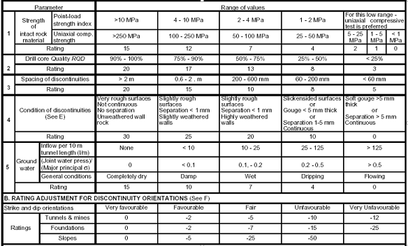
The following six parameters are used to classify a rock mass using the RMR system:
1. Uni axial compressive strength of rock material.
2. Rock Quality Designation (RQD).
3. Spacing of discontinuities.
4. Condition of discontinuities.
5. Groundwater conditions.
6. Orientation of discontinuities.

In applying this classification system, the rock mass is divided into a number of structural regions and each region is classified separately. The boundaries of the structural regions usually coincide with a major structural feature such as a fault or with a change in rock type. In some cases, significant changes in discontinuity spacing or characteristics, within the same rock type, may necessitate the division of the rock mass into a number of small structural regions.


 CLASSIFICATION PARAMETERS AND THEIR RATINGS

ROCK MASS CLASSES DETERMINED FROM TOTAL RATINGS:


Guidelines for excavation and support of 10 m span rock tunnels in accordance
with the RMR system (After Bieniawski 1989):


code for writing name in CNC simulator

G & M codes:
$AddRegPart 1 
G92z50
T1 M06
G00x40 y40 z2
G01z-5 F400 S 3000 M03
G01x45 y60
G01x50 y40
G01X47.5 y45 
G01x42.5
G01z2
G00x55 y40 z2
G01z-5 F400 S 3000 M03
G01y60
G01x57
G02y50 R5 
G01x55
G01x65 y40
G01z2
G00x70 y40 z2
G01z-5 F400 S 3000 M03
G03y50 R5
G02y60 R5
G01z2
G00x80 y40 z2
G01z-5 F400 S 3000 M03
G01x85 y60
G01x90 y40
G01X87.5 y45 
G01x82.5
G01z2
G00x95 y60 z2
G01z-5 F400 S 3000 M03
G01y40 
G01x105
G01z2
G00x110 y40 z2
G01z-5 F400 S 3000 M03
G01x115 y60 
G01x120 y40
G01X117.5 y45 
G01x113.5
G01z2
G00x125 y40 z2
G01z-5 F400 S 3000 M03
G01y60 
G01x135 y40
G01y60
G01z2
G00x40 y80 z2
G01z-5 F400 S 3000 M03
G01y100
G01x45 y90
G01X50 y100
G01y80
G01z2
G00x55 y85 z2
G01z-5 F400 S 3000 M03
G02I3 J0
G00x55 y85 z2
G01z-5 F400 S 3000 M03
G02I5 J0
G01z2
G00x30 y70 z2
G01z-5 F400 S 3000 M03
G01x150
G03y80 R5
G02y90 R5
G03y100 R5
G02y110 R5
G03y120 R5
G01x30
G03y110 R5
G02y100 R5
G03y90 R5
G02y80 R5
G03y70 R5
G02y60 R5
G03y50 R5
G02y40 R5
G03y30 R5
G01x150 R5
G03y40 R5
G02y50 R5
G03y60 R5
G02y70 R5
G01z40
M30

Saturday, 6 December 2014

Switch Mode Power supply (SMPS) with Active PFC and PC interface.

  1. Introduction:-
Switch mode power supply (SMPS) is a type of an electronic power converter which switches current at a fast rate to increase, decrease, regulate or condition the output voltage or current.
In other words like every other power supply SMPS transfers the power from input to the output like every other power supply but has many advantages in the department of efficiency, cost, size, weight and regulation.
That being said the most important aspect of a switch mode power supply is the high switching frequency. All SMPS operates at a very high switching frequency typically from 25 KHz to 1MHz.
  • Isolated.
  • Non-isolated
Isolated power supplies have an electrical isolated between input and output In order to achieve that a transformer is used.
Non-isolated power supplies do not have an electrical isolation between input and output. It uses an inductor for voltage conversions.


  1. Overview:-
The electric energy is not normally used in the form in which it was produced or distributed. Practically all electronic systems require some form of energy conversion. A device that transfers electric energy from a given source to a given load using electronic circuits is referred to as power supply. Of course, it does not really supply power, it just converts it, so "converter" is a more accurate term for such a device.
A typical application of a DC power supply unit (PSU) is to convert utility AC voltage into a set of regulated DC voltages required for electronic equipment. The energy flow in a modern PSU is controlled with power semiconductors, which can operate in different modes. In original systems they operated in linear mode. Nowadays in most PSUs semiconductors are continuously switching on and off with high frequency. Such units are referred to as switched mode power supplies or SMPS. They offer greater efficiency compared with linear supplies because they can control energy flow with low losses: when a switch is on, it has low voltage drop and will pass any current imposed on it; when it is off, it blocks the flow of current.
As the result, in such a switch the power dissipation which is the product of voltage and current, can be relatively low in both states. Switching mode units are also smaller in size and lighter in weight due to the reduced size of passive components and lower heat generation. The industry trend toward miniaturization, advancements in semiconductor technology, as well as various energy efficiency regulations have made "switcher" the dominant type of PSU across practically the full spectrum of applications. Most PSU manufactured today for AC input applications also include a PFC front end.
In general, SMPS converters can be classified into four types according to the form of input and output voltages: AC to DC (also called off-line DC power supply), DC to DC (voltage or current converter), AC to AC (frequency changer or cycloconverter), and DC to AC (inverter).


    1. Objectives:-
The objectives of the project are:-
  • Achieve high efficiency (>85%).
  • High power factor (>0.95).
  • Controlling and monitoring through a computer.
  • Universal input voltage.
  • Reduce mains noise and harmonics.
  • Minimize EMI (electromagnetic interference).
  • Implement variable voltage regulation
  • Minimize RFI (radio frequency interference).
    1. Power Factor:-
Power factor is the ratio of real power to apparent power:-
Real power (watts) produces real work; this is the energy transfer component (example electricity-to-motor rpm).Reactive power is the power required to produce the magnetic fields (lost power) to enable the real work to be done, where apparent power is considered the total power that the power company supplies.
When the power factor is not equal to 1, the current waveform does not follow the voltage waveform. This results not only in power losses, but May also cause harmonics that travel down the neutral line and disrupt other devices connected to the line. The closer the power factor is to 1, the closer the current harmonics will be to zero since all the power is contained in the fundamental frequency.
Since an SMPS uses DC voltage so the mains AC voltage is rectified and filtered, circuit is shown below:-
One problem with SMPS that they do not use any form of power factor correction is that, the input capacitor will only charge when input voltage is close to peak voltage or when input voltage is greater than the capacitor voltage. The capacitor discharges when the input voltage starts going lower than the peak voltage and re-charges when the peak approaches. A capacitor has a very low ESR (electrical series resistance) resulting in very high current when recharging. As a result the current only flows during the peak input voltages resulting in a highly distorted and peaky current waveform having a low power factor. Illustrated in the figure below:-
A switch mode power supply has a power factor of 0.5 to 0.6. Which by any standards is very low. Ideally power factor should be close to 1. With passive PFC, power factor can be improved up to 0.75. With active PFC it can be improved up to 0.99.


    1. Active Power Factor Correction (PFC):-
The power factor of an SMPS can be improved by smoothing out the peak currents. The current draw can be averaged out over the whole cycle improving the power factor. In order to do that the input capacitor have to charge over the whole cycle to accumulate energy.
The heart of active PFC is a boost converter. It is placed between the rectifier and input capacitor. So the boost converter receives a fully rectified AC line voltage with no bulk filtering. So the input voltage it receives ranges from zero to peak voltage to zero again. The frequency is twice the line frequency. It boosts the lower voltages to allow the input capacitor to charge during the dips in the input voltage. The boost converter is shown below:-
    1. PC Interface:-
In industries all the processes as automated i.e. controlled
by a computer for centralized control. All the sensor data is received by the computer which then further processes the data and acts accordingly. Power supply is the most important component in any electrical or electronic device. It’s monitoring and control is also necessary. It would be really convenient if it can be monitored and controlled through a centralized computer. It would also be easy to implement protections and current limiting through sensor data from the equipment being powered.
For PC interface an arduino would be used as it has an integrated USB interface. The output voltage and current would be monitored and the pulse width in the SMPS controller would be varied according to the voltage and current regulation values.
Related Work:


PCB designing ( simulation and hardware design )
    1. Studying Magnetic material
    2. Power electronics
    3. Soldering
    4. Mains voltage safety
    5. Protections
    6. Thermal management.
    7. Arduino development environment.


  1. Hardware and Software Requirements:
  1. Software:-
  1. Lab view.
  2. LTsplice
  3. Cadsoft eagle
  4. Arduino IDE

    1. Hardware:-
  1. Oscilloscope
  2. Multimeter.
  3. Dummy load.
  4. Power factor meter.
  5. Spectrum analyzer (for measuring harmonics).

  1. Advantages And Disadvantages of SMPS:-

  1. Advantages:

  • Much more efficient as compared to linear power supplies because it uses components as switches rather than resistive elements.
  • Protection against excessive output voltage by quick acting guard circuits
  • Smaller in size and lighter in weight.
  • Cheaper at higher power levels (sometimes in lower power as well).
  • Regulation is easy and efficient to implement.
  • Lower idle power consumption.

  1. Disadvantages:-
  • The circuit is much more complex as compared to linear PSUs.
  • EMI/RFI which is inherent in SMPS is difficult to suppress.
  • Electronic noise at the output and input terminals.
  • PCB layout is critical.


  1. Applications and Future:
Switch mode power supplies have applications in various areas. A switched-mode supply is chosen for an application when its weight, efficiency, size, or wide input range tolerance make it preferable to linear power supplies. Initially the cost of semiconductors made switch-mode supplies a premium cost alternative, but current production switch-mode supplies are nearly always lower in cost than the equivalent linear power supply.
In industrial and high power applications SMPS were not used because semiconductor devices were not rugged enough. But now many manufacturers have made rugged and powerful semiconductor devices. SMPS are now being developed and used in high power application offering cost and space savings.


Project timeline


TASK

Duration

Date

Literature review

1 month

September 2014

Choosing required Hardware

1 month

October 2014

Observation of Hardware

1 month

November 2014

Simulation (software) work

1 month

December 2014

Fabrication of PCB

1 month

January 2015

Installation of Hardware

1 month

February 2015

Testing and Result

1 month

March 2015

Progress Report

1 month

April 2015

Final Thesis

1 month

June 2015

Presentation and Demonstration


References:-

1) Application Note 42047 Power Factor Correction (PFC) Basics – Fairchild semiconductor.click

2) Power factor correction (PFC) handbook HBD853 – ON semiconductorpower factor correction

3) Power Factor Correction (PFC) Parts Selection Guide – Infineon.power factor

4) Control techniques for power factor correction converters - L. Rossetto, G.Spiazzi, P. Tenti

5) Power Supply Cookbook - Marty Brown.

6) Practical Switching Power Supply Design - Marty Brown

7) Switching Power Supply Design - Abraham I PressmenSPSD

8) Switch mode power supply reference manual – ON semiconductorB

BY Hashim Elahi university of engineering and Technology peshawar http://mobilezonex.blogspot.com/2014/02/home-made-switch-mode-power-supply.html