Thursday, 22 May 2014

Simulation of line coding scheme in Matlab


Manchester Coding Scheme:
Program :
data=[ 1 0 1 0 1 0  ];

i=1:length(data);
j=1.49:length(data)+0.49;
I=1.50:length(data)+0.50;
J=1.99:length(data)+0.99;
N=length(data);
time=[];
for k=1:length(data);
time=[time i(k),j(k),I(k),J(k)];
end

signal=[];
a=1;
prebit=1;

for t=1:length(data);
  
if(data(t)==0)
    signal(a:a+1)=1;
    signal(a+2:a+3)=-1;
      
elseif(data(t)==1)
    signal(a:a+1)=-1;
    signal(a+2:a+3)=1;
    
   
end
   
a=a+4;

end

plot(time,signal,'linewidth',4);
xlabel('time')
ylabel('signal')


Simulation Results


Differential Manchester Coding Scheme :
Program :
data=[ 1 0 1 0 1 0  ];

i=1:length(data);
j=1.49:length(data)+0.49;
I=1.50:length(data)+0.50;
J=1.99:length(data)+0.99;
N=length(data);
time=[];
for k=1:length(data);
time=[time i(k),j(k),I(k),J(k)]; %Time vector
end

signal=[];
a=1;
prebit=1;

%Signal Generation
for t=1:length(data);
    if(data(t)==0 && prebit==1)
        signal(a:a+1)=-1;
        signal(a+2:a+3)=1;
        prebit=1;
    elseif(data(t)==0 && prebit==-1)
        signal(a:a+1)=1;
        signal(a+2:a+3)=-1;
        prebit=-1;
    elseif(data(t)==1 && prebit==-1)
        signal(a:a+1)=-1;
        signal(a+2:a+3)=1;
        prebit=1;
    elseif(data(t)==1 && prebit==1) 
        signal(a:a+1)=1;
        signal(a+2:a+3)=-1;
        prebit=-1;

end
           a=a+4;
end
plot(time,signal,'linewidth',4); %Plot signal
title('Differential Manchester');
xlabel('Time');
ylabel('Differential Manchester');

%constellation diagram
   M = 4;
x = [0:M-1];
scatterplot(modulate(modem.pskmod(M),x));

Simulation Results :


Implementing  BPSK , QPSK and MFSK in Matlab

Program Code For BPSK 
clc;
clear all;
message=[1 1 0 0 1 0];
f_one=1.5;
fs=1000;% frequency
t=[0:1/fs:1];
A=5;
x=A*cos(2*pi*f_one*t+pi); %binary 0
y=A*cos(2*pi*f_one*t); %binary 1
time=t;
for i=1:length(message)-1;
    time=[time i+t];
end
%ask signal logic
ask_signal=[];
for i=1:length(message);
   if(message(i)==0)
       ask_signal=[ask_signal x];
   else
       ask_signal=[ask_signal y];
   end
end
   
plot(time,ask_signal,'linewidth',2);
xlabel('no of bits per second')
ylabel('signal value')

%constellation diagram BPSK
M = 2;
x = [0:M-1];
scatterplot(modulate(modem.pskmod(M),x));

Simulation :


Programme Code For MFSK :
clc; %clears the command window
clear all; %clears the workspace
message=[1 1 0 0 1 0 1 0 0]; %binary input is
                                                 
if (rem(length(message),3)~=0)     %for don’t care bits
    display('Error in Message'); 
end
f_one=1;
fs=1000; %frequency
t=[0:2/fs:1];
A=5;
w=A*cos(2*pi*f_one*t); %binary 000   (1 Hz)
x=A*cos(4*pi*f_one*t); %binary 001   (2 Hz)
y=A*cos(6*pi*f_one*t); %binary 010   (3 Hz)
z=A*cos(8*pi*f_one*t); %binary 011   (4 hz)
W=A*cos(10*pi*f_one*t);%binary 100   (5 Hz)
X=A*cos(12*pi*f_one*t);%binary 101   (6 Hz)
Y=A*cos(14*pi*f_one*t);%binary 110   (7 Hz)
Z=A*cos(16*pi*f_one*t);%binary 111   (8 Hz)
time=t;
for i=1:(length(message)/3)-1;
    time=[time i+t];
end
%ask signal logic
ask_signal=[];
for i=1:3:length(message);
   if(message(i)==0 && message(i+1)==0 && message(i+2)==0)
       ask_signal=[ask_signal y];
   elseif(message(i)==0 && message(i+1)==0 && message(i+2)==1)
       ask_signal=[ask_signal z];
   elseif(message(i)==0 && message(i+1)==1 && message(i+2)==0)
       ask_signal=[ask_signal x];
   elseif(message(i)==0 && message(i+1)==1 && message(i+2)==1)
       ask_signal=[ask_signal w];
   elseif(message(i)==1 && message(i+1)==0 && message(i+2)==0)
       ask_signal=[ask_signal W];
   elseif(message(i)==1 && message(i+1)==0 && message(i+2)==1)
       ask_signal=[ask_signal X];
   elseif(message(i)==1 && message(i+1)==1 && message(i+2)==0)
       ask_signal=[ask_signal Y];
   elseif(message(i)==1 && message(i+1)==1 && message(i+2)==1)
       ask_signal=[ask_signal Z];
   end
end
   %figure
   plot(time,ask_signal,'linewidth',2);
   xlabel('no of bits per second');
   ylabel('signal value');
    
% constellation diagram
inphase = [1 1 1 1 1 1 1 1];
quadr = [0 0 0 0 0 0 0 0];
 const = inphase + j*quadr;
scatterplot(const,1,0,'*');
axis([-3 3 -3 3]); 

Simulation :


Programme Code For QPSK :

clc; %clears the command window
clear all; %clears the workspace
message=[1 1 0 0 1 0]; %binary input is
                                                 
if (rem(length(message),2)~=0)     %for don’t care bits
    message(1,length(message)+1)=1; 
end
f_one=1.5;
fs=1000; %frequency
t=[0:2/fs:1];
A=5;
w=A*cos(2*pi*f_one*t+pi/4);%binary 11
x=A*cos(2*pi*f_one*t+3*pi/4); %binary 01
y=A*cos(2*pi*f_one*t-3*pi/4); %binary 00
z=A*cos(2*pi*f_one*t-pi/4); %binary 10
time=t;
for i=1:(length(message)/2)-1;
    time=[time i+t];
end
%ask signal logic
ask_signal=[];
for i=1:2:length(message);
   if(message(i)==0 && message(i+1)==0)
       ask_signal=[ask_signal y];
   elseif(message(i)==1 && message(i+1)==0)
       ask_signal=[ask_signal z];
   elseif(message(i)==0 && message(i+1)==1)
       ask_signal=[ask_signal x];
   elseif(message(i)==1 && message(i+1)==1)
       ask_signal=[ask_signal w];

end
end

%figure
plot(time,ask_signal,'linewidth',2);
xlabel('no of bits per second');
ylabel('signal value');
    
% constellation diagram
inphase = [1 -1 1 -1];
quadr = [1 1 -1 -1];
inphase = [inphase; inphase]; inphase = inphase(:);
quadr = [quadr; quadr]; quadr = quadr(:);
const = inphase + j*quadr;
scatterplot(const,1,0,'*');
     
axis([-3 3 -3 3]);


Simulation :


how to find out fault in cars in a seconds


Abstract:- 
On-Board Diagnostic System is a new dimension in the field of Automobiles. It is a core element of all the modern day vehicles and can enhance Vehicle’s performance by periodic inspections. OBD-II provides access to data from the engine control unit (ECU) and offers a valuable source of information when troubleshooting problems inside a vehicle. It provides almost complete engine control and also monitors parts of the chassis, body and accessory devices, as well as the diagnostic control network of the car.
Introduction:- 
On-Board Diagnostics, Second Generation (OBD-II) is a set of standards for implementing a computer based system to control emissions from vehicles. It was first introduced in the United States in 1994, and become a requirement on all 1996 and newer US vehicles. Other countries, including Canada, parts of the European Union, Japan, Australia and Brazil adopted similar legislation but some countries like Pakistan still uses older version i.e. OBD-I. A large portion of the modern vehicle fleet supports OBD-II or one of its regional flavors (EOBD, JOBD etc.). Among other things, OBD-II requires that each complaint vehicle be equipped with a standard diagnostic connector (DLC) and describes a standard way of communicating with the vehicle’s computer also known as the ECU (Electronic Control Unit). A wealth of information can be obtained by tapping into the OBD bus, including the status of the malfunction indicator light (MIL), diagnostic trouble codes (DTCs), inspection and maintenance (I/M) information, freeze frames, VIN, Hundreds of real-time parameters, and more.
Objectives:- 
This application can be used to get an idea of how the engine management diagnostic tools work. Machinery health monitoring or engine management components mainly focused on the ECU and a generic scan tool based on OBD-II Protocol.  OBD –II protocol is extensively used to fetch engine parameters. These parameters will be used by the software for tracking and management purposes. Every vehicle used its own specific OBD-II company protocols which only compatible with specific vehicles. 
Now our objective is to put all OBD-II protocols in OBD using STN1110 IC and make such type of algorithm that search a specific protocol which is compatible for every type of vehicle. Further we will design OBD hardware module for it if needed. We will mainly focus on OBD-II protocol. 


Literature Review:-
We did an online survey and found the following topics related to our project.
OBD-II
An OBD-II compliant vehicle can use any of the five communication protocols, i.e. SAE J1850 PWM, SAE J1850 VPM, ISO9141-2 and ISO14230-4 (KWP2000) and since 2003 also ISO 15765-4/SAE J2480. ELM-USB and OBD tester support all of them.
Some models are equipped with SAE J1962 connector, but these cars are NOT OBD-II complaint. Typical examples of such cars are some early VW/Skoda/ seat models, Ford cars with EEC-IV using Ford DCL protocol (e.g. Ford Escort), Nissan EU/Asian models (using Nissan DDL protocol), or some European Hyundai Models.
Determining protocol from OBD-II pinout
As a general rule, we can determine which protocol our vehicle is using by looking at the pin out of the OBD-II connector. The following table shows this.
 
Standard                   Pin 2               Pin 6             Pin 7    Pin 10      Pin 14        Pin 15   
J1850 PWM     must have - -                          must have - -   
J1850 VPW         must have - - - - -   
ISO9141/14230 - -                                  must have - -                          optional   
ISO15765 (CAN) -                   must have - -                        must have -  

 
Figure 1


ECU
In automotive electronics, ECU is a generic term for any embedded system that controls one or more of the electrical system or subsystems in a motor vehicle.
Types of ECU include electronic/engine control module (ECM), powertrain control module (PCM), Transmission Control module (TCM), brake control module (BCM or EBCM), central control module (CCM), central timing module (CTM), general electronic module (GEM), body control module (BCM), suspension control module (SCM). Taken together, these systems are sometimes referred to as the car’s computer.
Some modern motor vehicles have up to 80 ECUs. Managing the increasing complexity and number of ECUs in a vehicle has become a key challenge for original equipment manufacturers (OEMs).
ELM 327
The ELM327 is a programmed microcontroller produced by ELM Electronics for translating the OBD interface found in most modern cars. The ELM327 command protocol is one of the most popular PC to OBD interface standards, and is also implemented by other vendors.
ELM 327
The STN1110 integrated circuit is an OBD to UART interpreter that can be used to convert messages b/w any of the OBD-II protocols currently in use and UART. It is fully compatible with the de-facto industry standard ELM328 command set. Based on a 16-bit processor core, the STN1110 offers more features and better performance than any other ELM327 compatible IC.
Methodology:-
STN1110 is the world’s smallest, lowest cost multiprotocol OBD to UART Interpreter IC.  The main task of our project is to design hardware for STN1110 IC and interface STN1110 with pc and also interface with OBD 2 via Bluetooth or WIFI for checking that it is compatible for different vehicles or not. If it is not computable for our required vehicles then we design hardware and different algorithm for our required vehicles which will search specific protocol for specific vehicle.
 

Application:-
The applications of OBD ranges from simple generic consumer level tools to highly sophisticated original equipment manufacturer (OEM) dealership tools to vehicle telematic devices. A range of rugged hand-held scan tools is available that use OBD as simple fault code readers/reset tool. OBD system can monitor the engine pollutants emission level continuously and show faults timely. Also it can control the vehicles emission level effectively and avoid the higher fuel consumptions and emissions caused by sustained driving of fault vehicles. OBD system provides a convenient means for vehicle maintenance and repair, and the real time data provide related research and analysis with the basis. It has great significance and high application value for improving vehicle maintenance.
Requirements 
Hardware:  Development PC: PC with MS Windows XP or Window 7 or Window 8
Minimum Display Resolution: 1024 * 768 with 16 bit color
Server PC: PC with 1TB hard drive
 ECUs OBD STN 1110 ELM327 some extra hardware.
Software: Assembly language for STN 1110
References:-
project perform by
Shawkat Ali 10PWCSE0868
Saba Kanwal 10PWCSE0860
Amjad Ali 10PWCSE0889
Maria Shaukat 10PWCSE0864


Wednesday, 21 May 2014

Implementing Spread Spectrum Communication in Matlab


DSSS  is  a  wireless  analog  encoding  scheme  based  on  a  technique   spread  spectrum.  
It represents each data bit by multiple bits in the transmitted signal using a chip code/spreading code. The spreading code spreads the signal across a wider frequency band in direct proportion to the length of the chip code. 

Task 1: Study and implement the  matlab functions and show the output:
Hadamard:
This MATLAB function returns the Hadamard matrix of order n.
Syntax:
Hadamard(n) % n n must be an integer and n, n/12 or n/20 must be a power of 2.
Command: Hadamard(4);
Output: 
     1     1     1     1
     1    -1     1    -1
     1     1    -1    -1
     1    -1    -1     1
randperm
It stands for random permutation
Syntax:
P = randperm(n); % returns a row vector containing a random permutation of the integer from 1 to n inclusive.
P= randperm(n,k) % return a row vector containing k unique integers selected randomly from 1 to n inclusive. 
Command: 
randperm(7);
output:  6     3     7     5     1     2     4
Command:
Randperm(7,3);
Output:
                     6     2     7

randint
It generates a matrix of uniformly distributed random integers.
Syntax:
Out= randint % generate either 0 or 1
Out = randint(n) % generate a matrix of order nxn containing randomly 0’s and 1’s.
Out = randint(n,m,range)% generates a matrix of order nxm, if rg is 0 it will generate matrix containing all zeros, otherwise it will have integer containing in the specified range.
Command:   randint(2,2,9)
                  Output:8     4
              4     2
biterr
It computes the number of bit errors and bit error rate(BER).
Syntax:
 [number, ratio]= biterr(x,y) % compare the unsigned binary representation of each element of x matrix with that of y matrix.
[number, ratio]= biterr(x,y,k) % it considers that elements of x and y have k bits.
[number, ratio]= biterr(x,y,k,flg) % flg can be ‘overall’ (element by element comparison), ‘rsow_wise’  (compare nth row of x with nth row of y) and ‘column_wise’. 
[number,ratio, individual]= biterr(….) % individual have dimension greater then that of x and y matrix. Each element of individual represent the difference of bits between the corresponding elements of x and y matrix and number of comparisons.
Command:
[number,ratio,individual] = biterr([0;0;0],randi([0 1],3,5));
Output:
number = 2              1              2              1              1       
                 ratio =  2/3            1/3            2/3            1/3            1/3     
                 individual =0              0              0              1              0       
                     1              0              1              0              1       
                     1              1              1              0              0       
bi2de
convert binary vector to decimal equivalent number.
Syntax:
Bin2de(v)
Command:   v=[1 0 1 0 1]
bi2de(v);
Output= 21
bin2gray
Converts binary integer to corresponding  Gray-encoded integer.
Syntax: 
Y= bin2gray(x,modulation,M)
or 
[y,map]= bin2gray(x,modulation,M) 
Code:
% To Gray encode a vector x with a 16-QAM Gray encoded
 % constellation and return its map, use:
 x=randi([0 5],1,100);
 [y,map] = bin2gray(x,'qam',16);
 % Obtain the symbols for 16-QAM
 hMod = modem.qammod('M', 16);
 symbols = hMod.Constellation;
 % Plot the constellation
 scatterplot(symbols);
 set(get(gca,'Children'),'Marker','d','MarkerFaceColor',...
 'auto'); hold on;
 % Label the constellation points according
 % to the Gray mapping
 for jj=1:16
 text(real(symbols(jj))-0.15,imag(symbols(jj))+0.15,...
 dec2base(map(jj),2,4));
 end
 set(gca,'yTick',(-4:2:4),'xTick',(-4:2:4),...
 'XLim',[-4 4],'YLim',...
 [-4 4],'Box','on','YGrid','on', 'XGrid','on');
Output:


de2bi
It converts decimal number to equivalent binary  vector.
Command: de2bi(3)
Output:  1 0 1
gray2bin
Convert Gray-encoded positive integers to corresponding Gray-decoded integers.
Syntax: 
Y= gray2bin(x,Modulation, M);
or
[Y,map]= gray2bin(x,Modulation,M);
Code:
% To Gray decode a vector x with a 16-QAM Gray encoded
 % constellation and return its map, use:
 x=randi([0 15],1,100);
 [y,map] = gray2bin(x,'qam',16);
 % Obtain the symbols for 16-QAM
 hMod = modem.qammod('M', 16);
 symbols = hMod.Constellation;
 % Plot the constellation
 scatterplot(symbols);
 set(get(gca,'Children'),'Marker','d','MarkerFaceColor','auto');
 hold on;
 % Label the constellation points according
 % to the Gray mapping
 for jj=1:16
  text(real(symbols(jj))-0.15,imag(symbols(jj))+0.15,...
  dec2base(map(jj),2,4));
 end
 set(gca,'yTick',(-4:2:4),'xTick',(-4:2:4),...
  'XLim',[-4 4],'YLim',...
   [-4 4],'Box','on','YGrid','on', 'XGrid','on');

Output:


vec2mat
It converts a vector into matrix.
Command: v=[1 2 3 4 5];
 vec2mat(v);
Output: 1    2    3
               4    5    0

Task 2:  Implement DSSS receiver in Matlab and show the complete results:
Matlab code: 
At transmitter side the data=[1 0 1 1 1 1] was encoded as coded=[1 -1 -1 1 -1 1 1 -1 -1 1 1 -1 1 -1 -1 1 1 -1 -1 1 -1 1 1 -1 1 -1 -1 1 -1 1 1 -1 1 -1 -1 1 -1 1 1 -1 1 -1 -1 1 -1 1 1 -1];  by  spread  spectrum technique.
Matlab function for receiver side.
coded=[1 -1 -1 1 -1 1 1 -1 -1 1 1 -1 1 -1 -1 1 1 -1 -1 1 -1 1 1 -1 1 -1 -1 1 -1 1 1 -1 1 -1 -1 1 -1 1 1 -1 1 -1 -1 1 -1 1 1 -1];
ct=hadamard(8);
p=8;
code=ct(p,1:end)';
data=[];
l=length(coded);
for i=1:8:l
    matrix=coded(1,i:i+7);
    original=(matrix*code)/length(code);
    if(original ==-1)
        original=0;
    else
        original=1;
    end
    data=[data original];
    end
Data:    1 0 1 1 1 1
Coded data received from transmitter: 1 -1 -1 1 -1 1 1 -1 -1 1 1 -1 1 -1 -1 1 1 -1 -1 1 -1 1 1 -1 1 -1 -1 1 -1 1 1 -1 1 -1 -1 1 -1 1 1 -1 1 -1 -1 1 -1 1 1 -1
Decoded data at Receiver:  1 0 1 1 1 1
Task 3:  Implement Frequency Hopping Spread Spectrum (FHSS) Transmitter in Matlab and show the complete results.
Frequency-hopping spread spectrum (FHSS) is a method of transmitting radio signals by rapidly switching a carrier among many frequency channels, using a pseudorandom sequence known to both transmitter and receiver. It is used as a multiple access methodin the frequency-hopping code division multiple access (FH-CDMA) scheme
Matlab code for transmitter: 
      clc
clear all
close all 
data=[1 0 1 1 1 1]; 
size=length(data); 
M=2; 
NRZ_signal=[]; %unipolar NRZ signal 
k=[];
for (t=1:size) 
    if (data(t)==0)
        NRZ_signal(t)=-1;
    else
        NRZ_signal(t)=1;
    end
    k=[k NRZ_signal(t)];
end
rand_freq=[2 3 4 5 6 7 8 9];
chip=8;
r=randperm(chip);
t=[];
bpsk_datasig=[];
for b=1:length(k)
   f=rand_freq(r(b));
    fs=50;
    t1=b-1:1/fs:b;
    t2=0:1/fs:1;
    x=cos(2*pi*f*t2);
    y=sin(2*pi*f*t2);
    t=[t t1];
     if (k(b)==1) 
            a=x; 
        else
            a=y;
        end
 bpsk_datasig=[bpsk_datasig a];
end
plot([1:length(bpsk_datasig)], abs(fft(bpsk_datasig)));

capturing data through ethereal


Ethereal:
Ethereal is a network packet analyzer, which captures network packets and displays that packet data detailed as possible. In fact, it’s kind of a measuring tool that tries to measure what is going inside a network cable. It can be downloaded from www.ethereal.org
download ethereal

 Few main uses of Ethereal can be 
1. Network administrators can use it to troubleshoot network problems 
2. Network security engineers use it to examine security problems. 
3. Developers use it to debug protocol implementation. 
4. And we students will learn the basics of computer networks with its help. 

Task 02:
Capture data on the network using all the three auto-stop features i.e:


a) Packets-Based:
No of data packets captured =35 


b) Size-Based: Data captured about 1Mbytes.


c) Time Based : Data captured for 30 seconds is ;

  
Task 02: Filter on the capturing process on the basis of ;
Distination IP :
   

Port number : port (80)

  
Task 3 :
SMTP Protocol :

  
Findings:
Packet size = 423 bytes
Header size = 20 bytes
Checksum value = 0x2498 [validation disabled]
Time with refrence to the first packet = 0.12393000 sec
Source IP Address = 82.178.158.19
Destination IP Address = 10.110.160.100
Source MAC address = 7c:ad:74:e4:f6:d0
Destination MAC address = o8:ed:b9:86:6d:
Note, to view the image it is better to download it first.

Introduction to Ethereal

Objectives

What is ethereal and why we study it?
How does ethereal works and what are its main features?
Introduction to ethereal interface and its menu items

Ethereal 

Ethereal is the network packet analyzer, which captures network packets and displays that packet data as detailed as possible. It is kind of measuring tool that tries to measure what is going inside a network cable.

Why Study Ethereal ?

Study of ethereal is important because being a student of data communications one must know how information is transferred between functional units by means of data transmission according to a protocol .Also it helps in knowing how information is transferred in computer networks.

Uses of Ethereal

Network administrator can use it to troubleshoot network problems
Network security engineers use it to examine security problems
Developers use it to debug protocol implementation


Task 1
a)Find the available interfaces on the computer and the IP assigned to each interface.


b)Capture packets on a particular interface,find out what protocols have been used,and save them in a file.
Captured the Microsoft interface whose IP Address is 192.168.1.2.
The following are the protocols used:
1)TCP
2)UDP
3)ARP
4)RUDP
 

c) State your findings
The findings are:
1 ) Data can be captured from the wire from a live network connection.
2) Data display can be refined using a display filter.
3) You can capture, filter, and analyze data your network adapter sees -- nothing more and nothing less. Typically it is used to examine what data is being sent to and from your machine. If there's strange network activity going on, wireshark will certainly tell you about it. In that sense, it is a security tool. It's also valuable for debugging software you write yourself that works over the network. 

Thursday, 15 May 2014

Home Automation using GSM and Arduino :


Main purpose is to provide the user with comfort and access to control his devices from anywhere in the world.
  The user can control his home appliances like air conditioners, fans, lights or music systems etc from anywhere in the world by just sending  a simple pre-defined SMS command to a particular number, user received the acknowledgement for his action. User can check the status whether his device is on or off at that moment. 

Automatic gates for his house or garage, IR motion sensors or smoke or fire alarms can also be added to alert the user in case of any emergency situations by SMS  and by using  GPS  it can send  SOS message to rescue teams with exact location. 

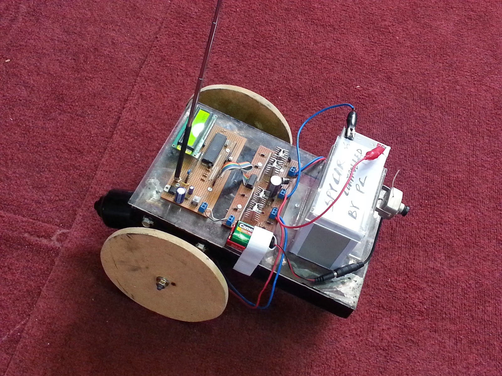
Spy Car controlled by Pc :


Radio frequency is used, through pc you establish a connection using hyper terminal and serial cable. And then through hyper terminal you can control the car`s direction and motion.
   Wireless camera is attached to the infront of this car, for spying or monitoring purposes, and an integrated mic is also located inside the camera module, so you can watch and hear the surrounding by an AV receiver.


GSM modem can be introduced and we can control its direction through sms commands, GPS for tracking , different sensors like temperature , smoke radiations etc . an android app can also be developed to control its direction and motion and even watch the video being captured by the wireless camera on the car.